...
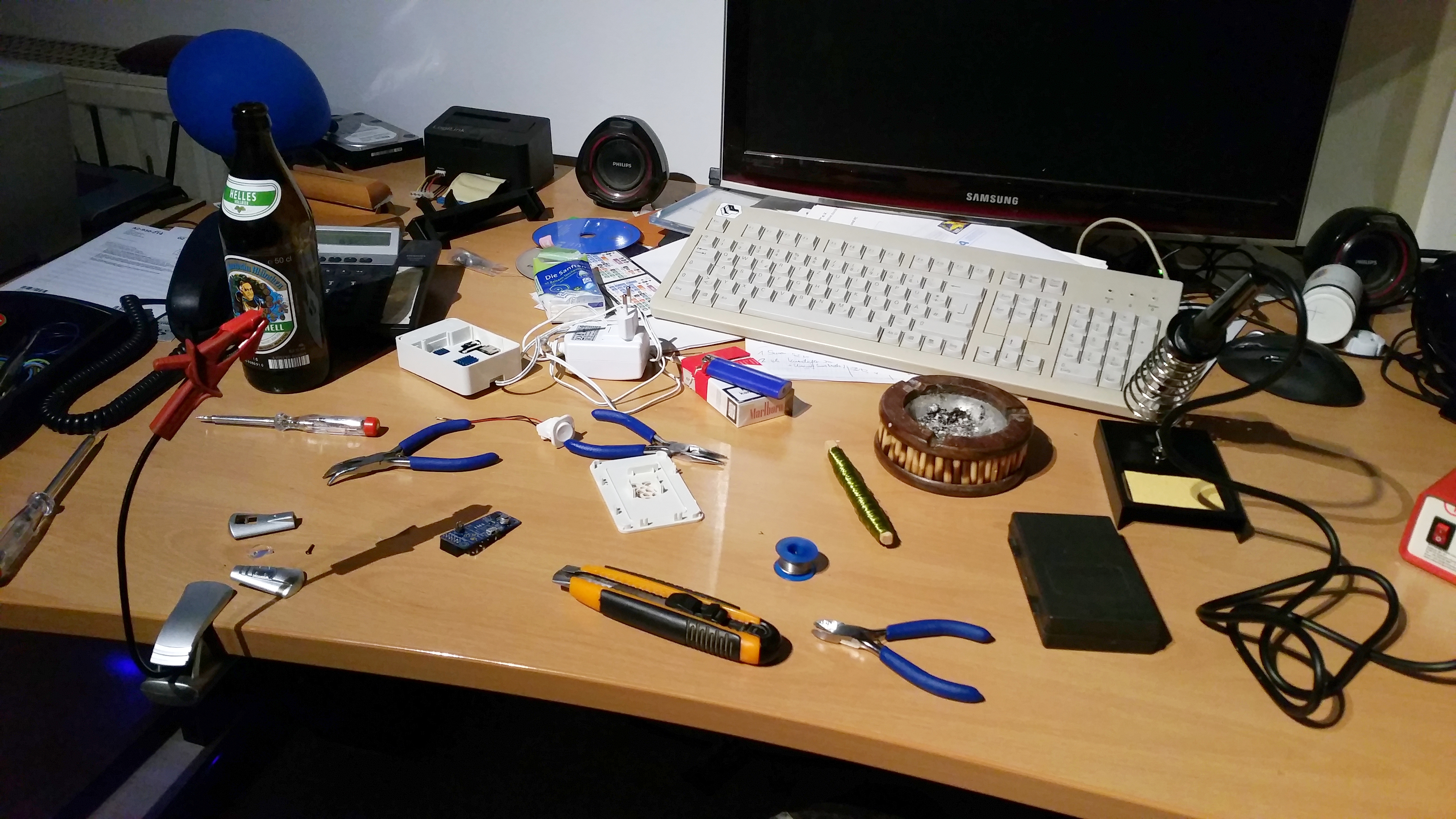
First: Grab yourself a beer (Augustiner will do best) and get comfortable. I did, as you can see ;)
For reference, I will list the tools I used for this project. Feel free to use better suited and more professional gear (especially, if you're more into crafting than me, which I bet is the case).
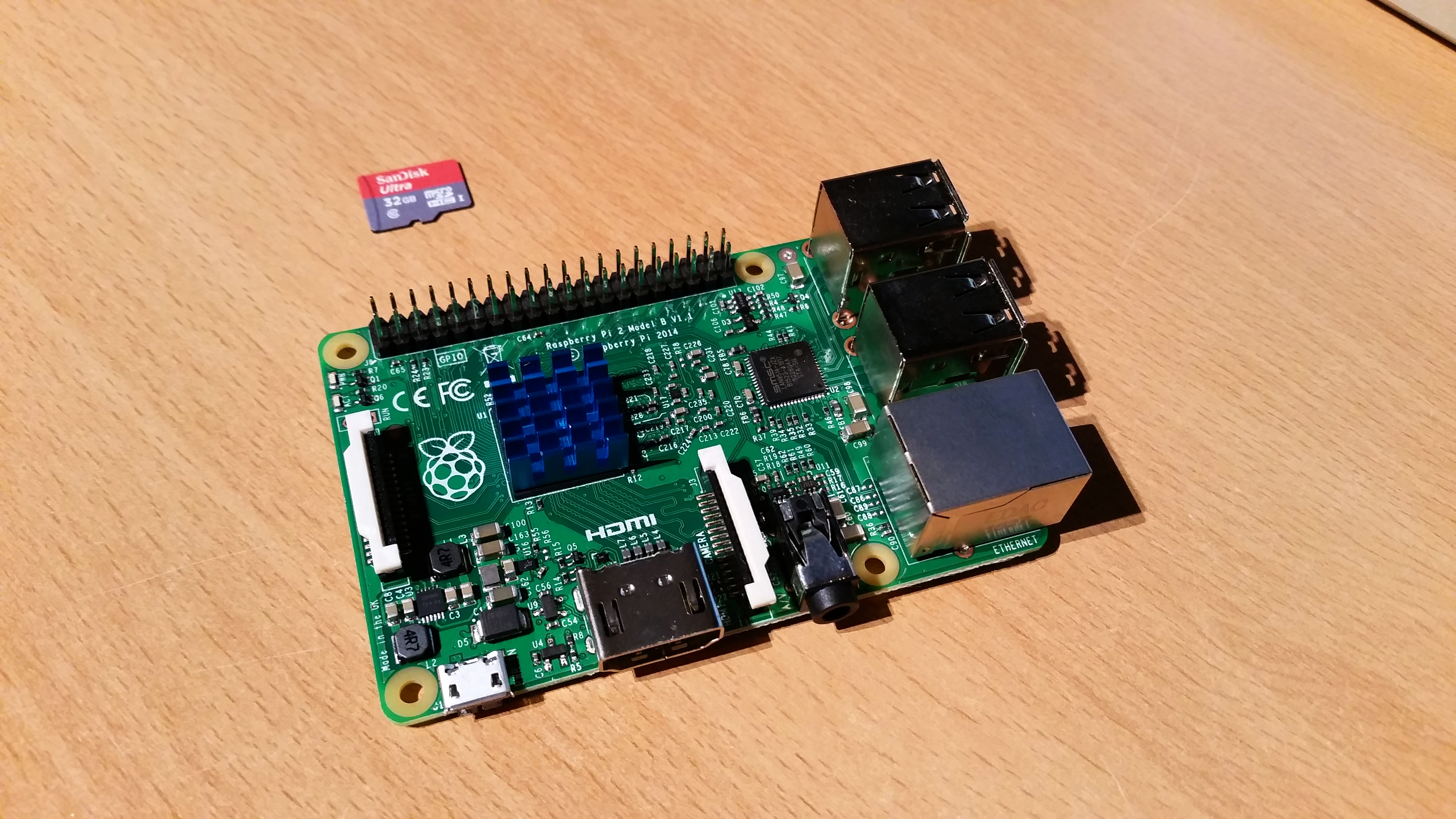
Raspberry Pi 2, Model B. With it's high specs and built-in video decoders the perfect match for this project. Plus: I just recently decided to give the RPi a try at the time and this was the model en vogue.
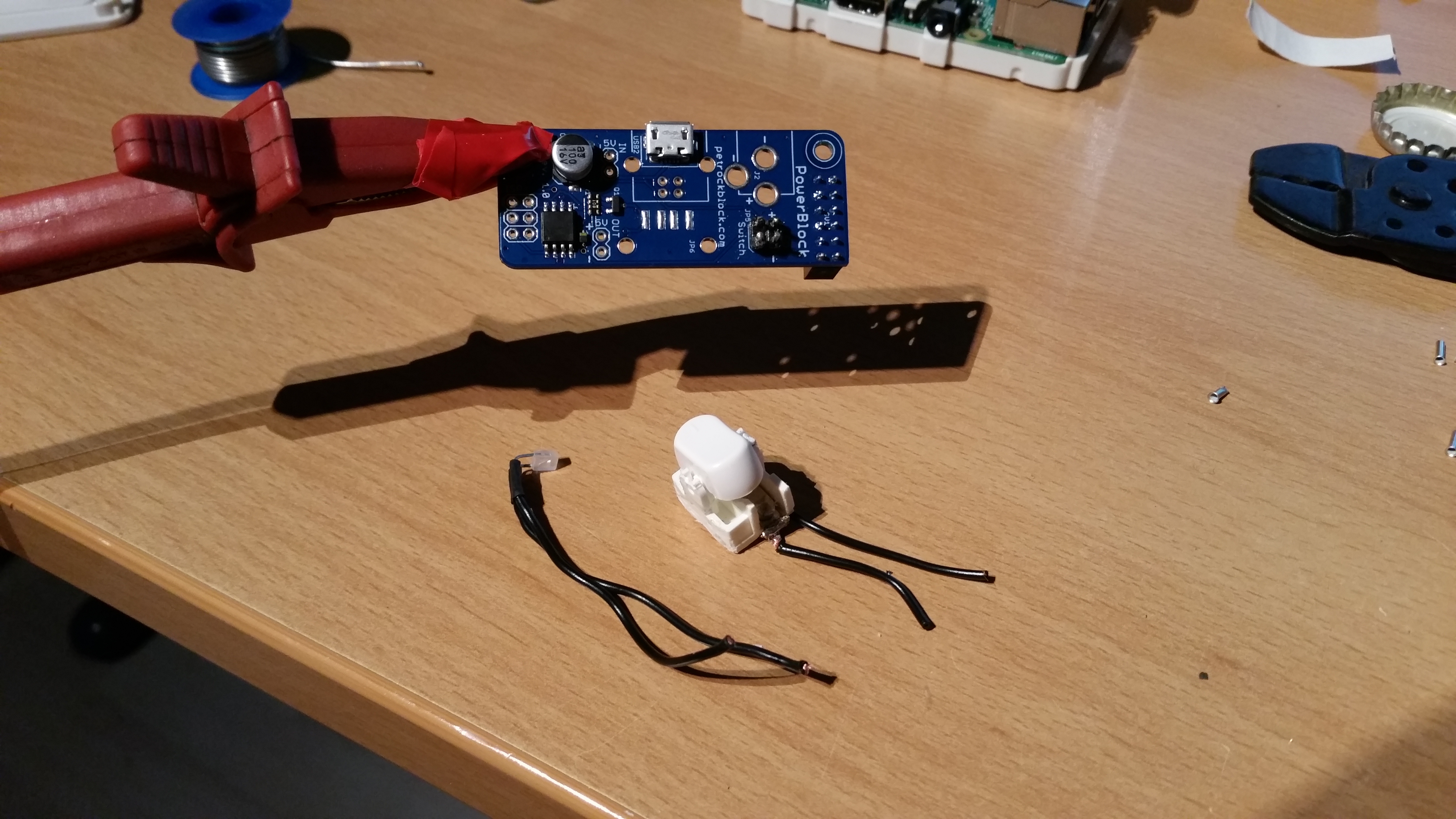
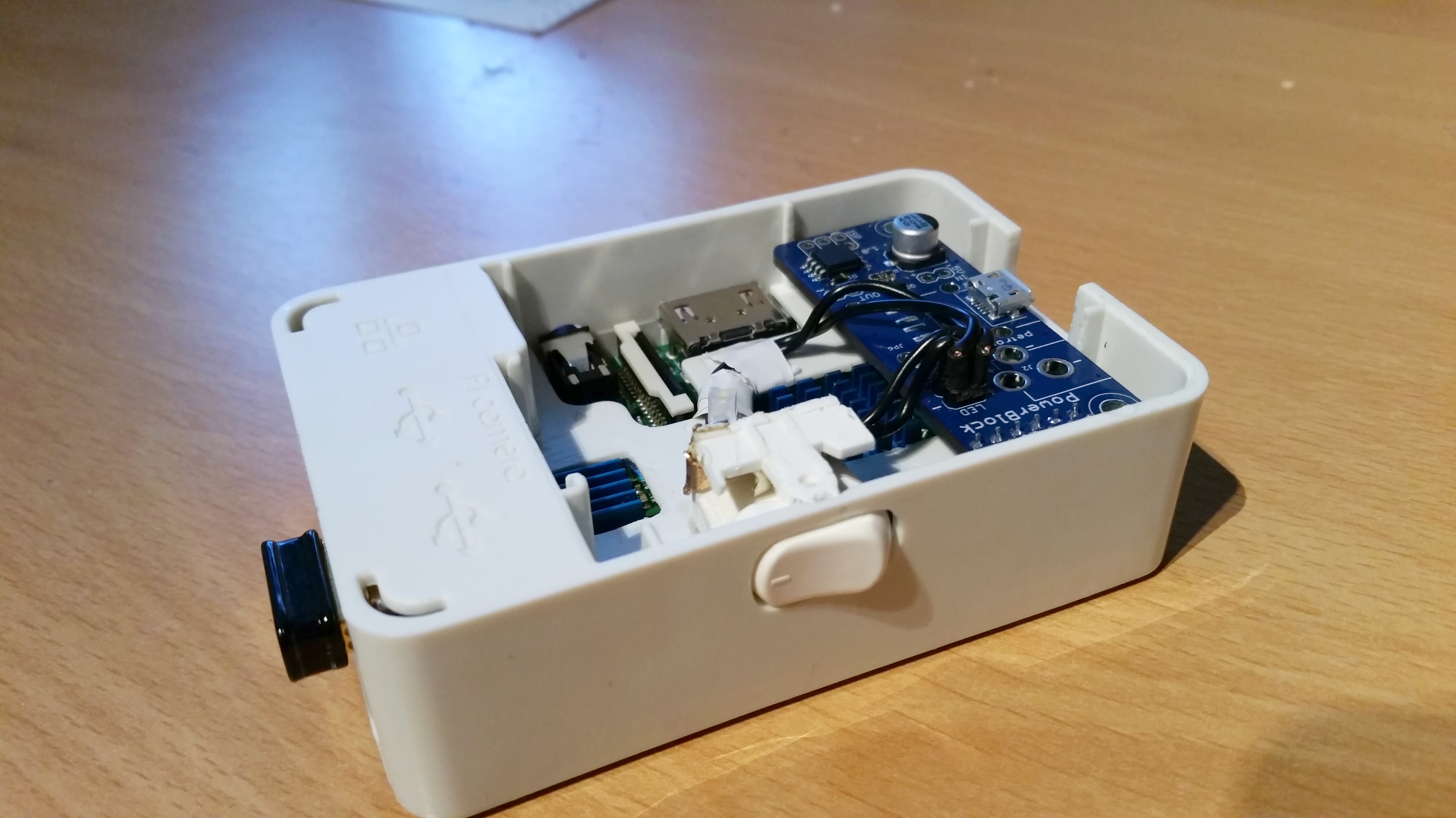
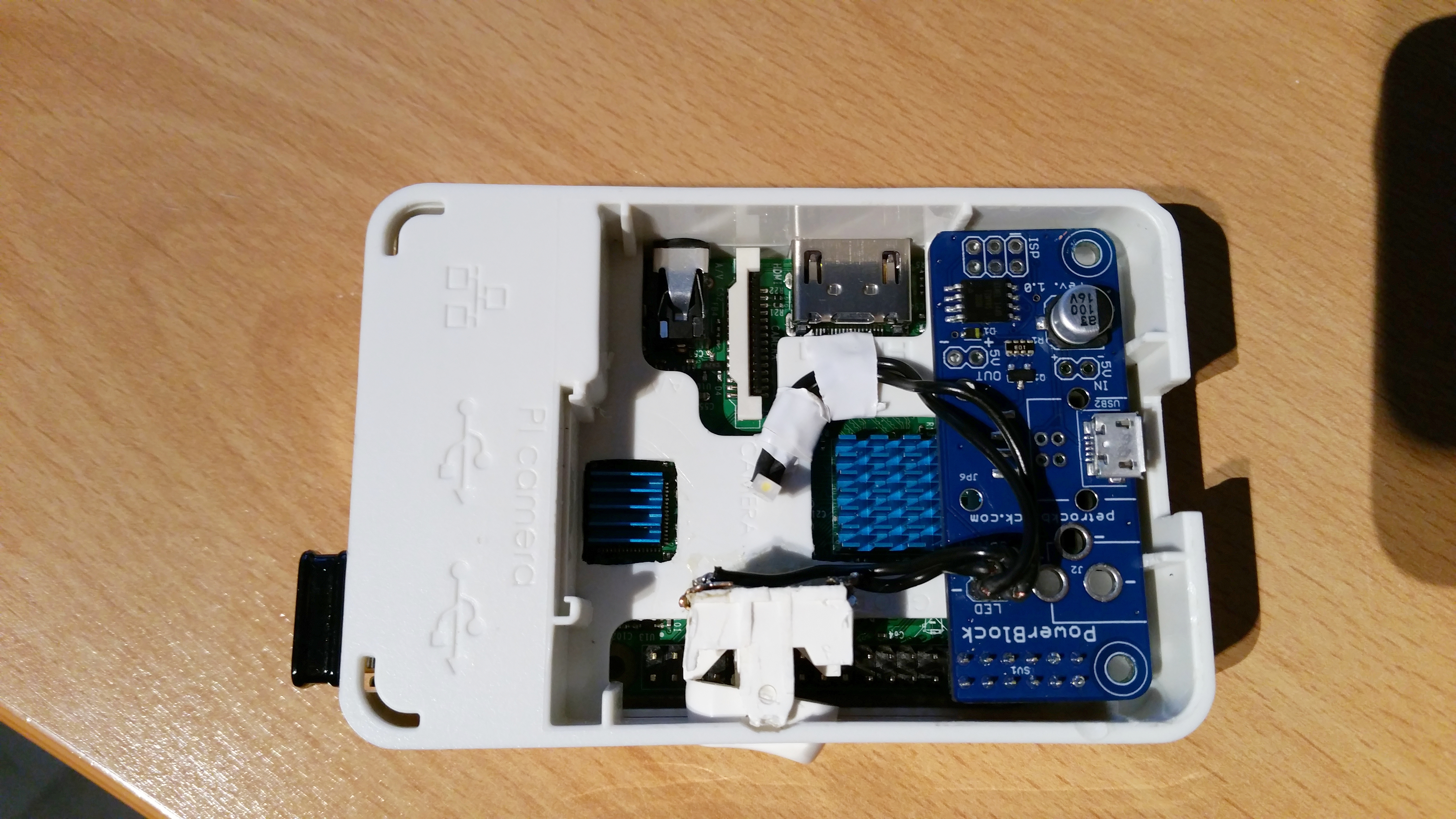
This is an add-on board called PowerBlock from the RetroPie project. It is used for connecting the switch and LED. It also protects the Pi from current spikes. A must have, if you ask me. Also, Florian from petrockblog is a great and genius person. Give his boards and the incredible retro gaming distribution RetroPie a try
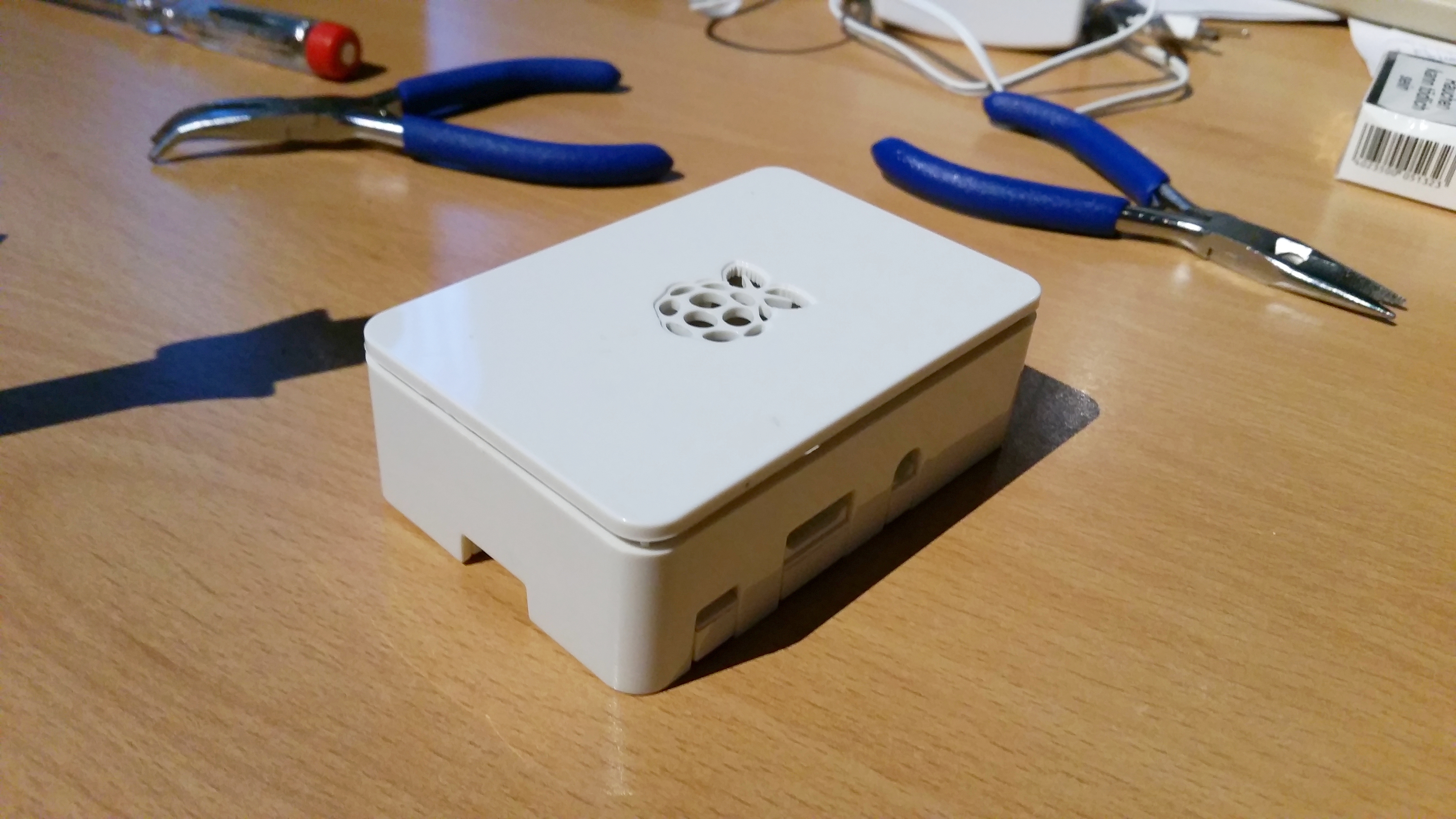
An ordinary OneNineDesign case, which soon will never be the same again. Poor little thing ;)
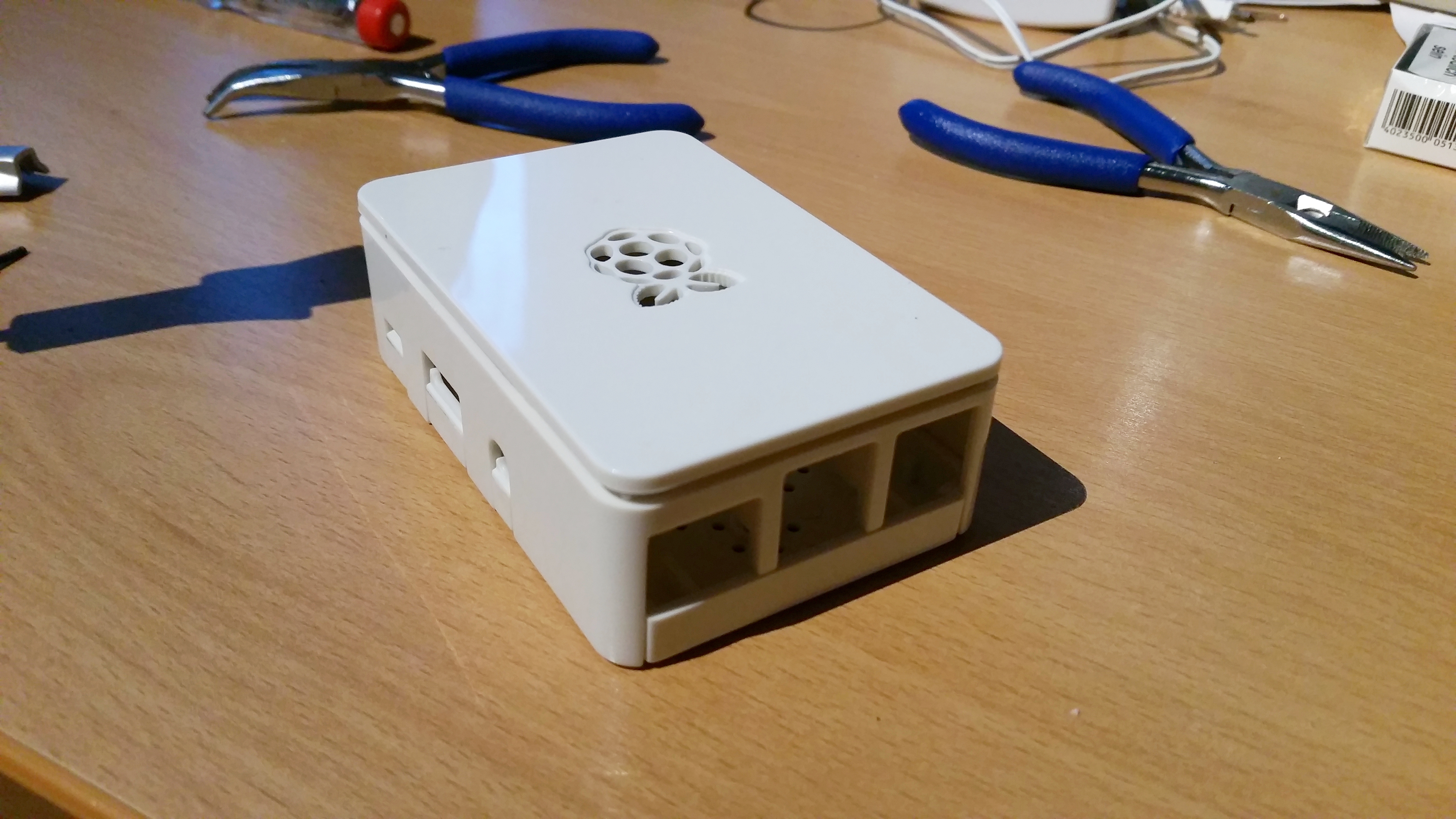
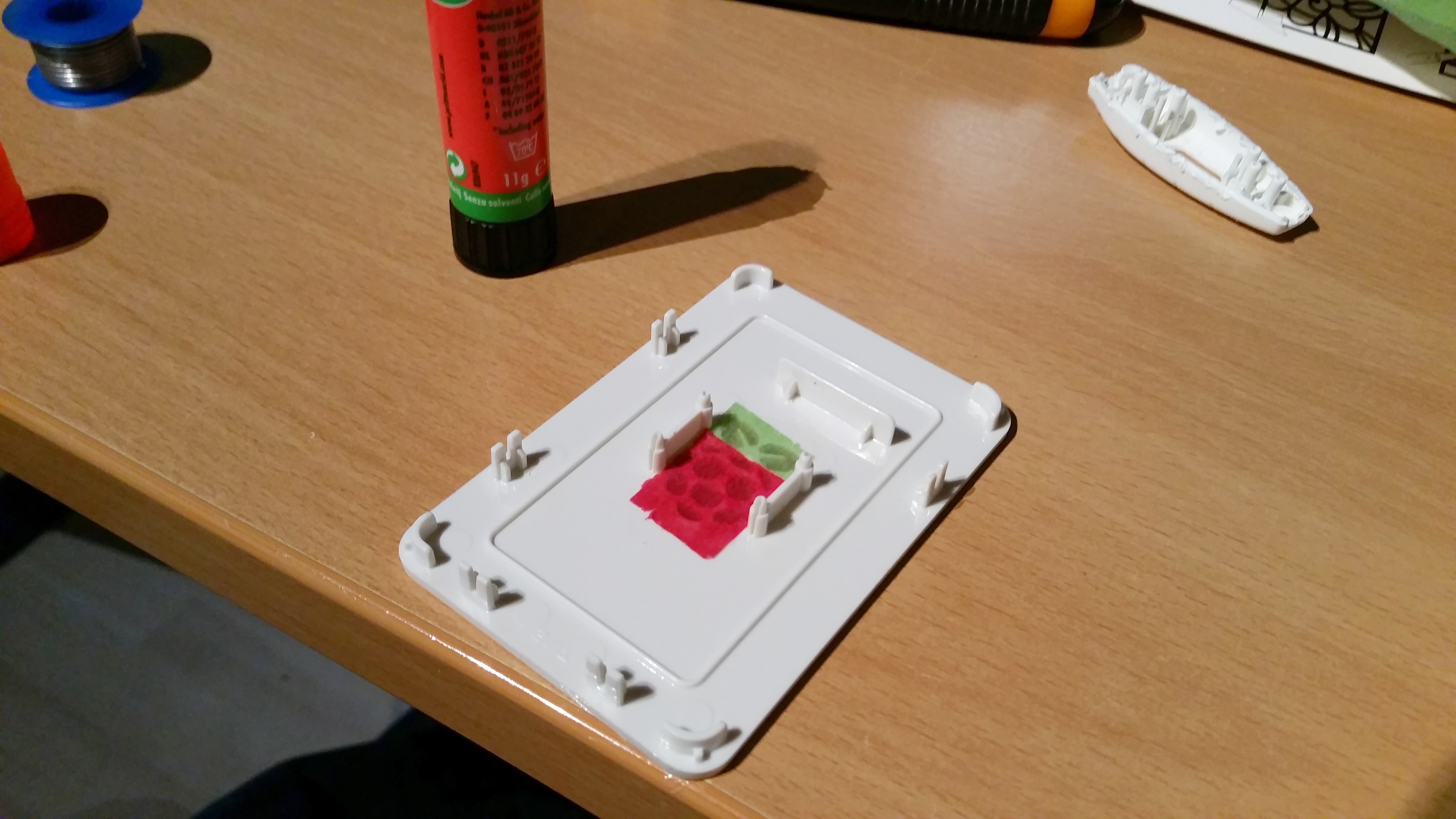
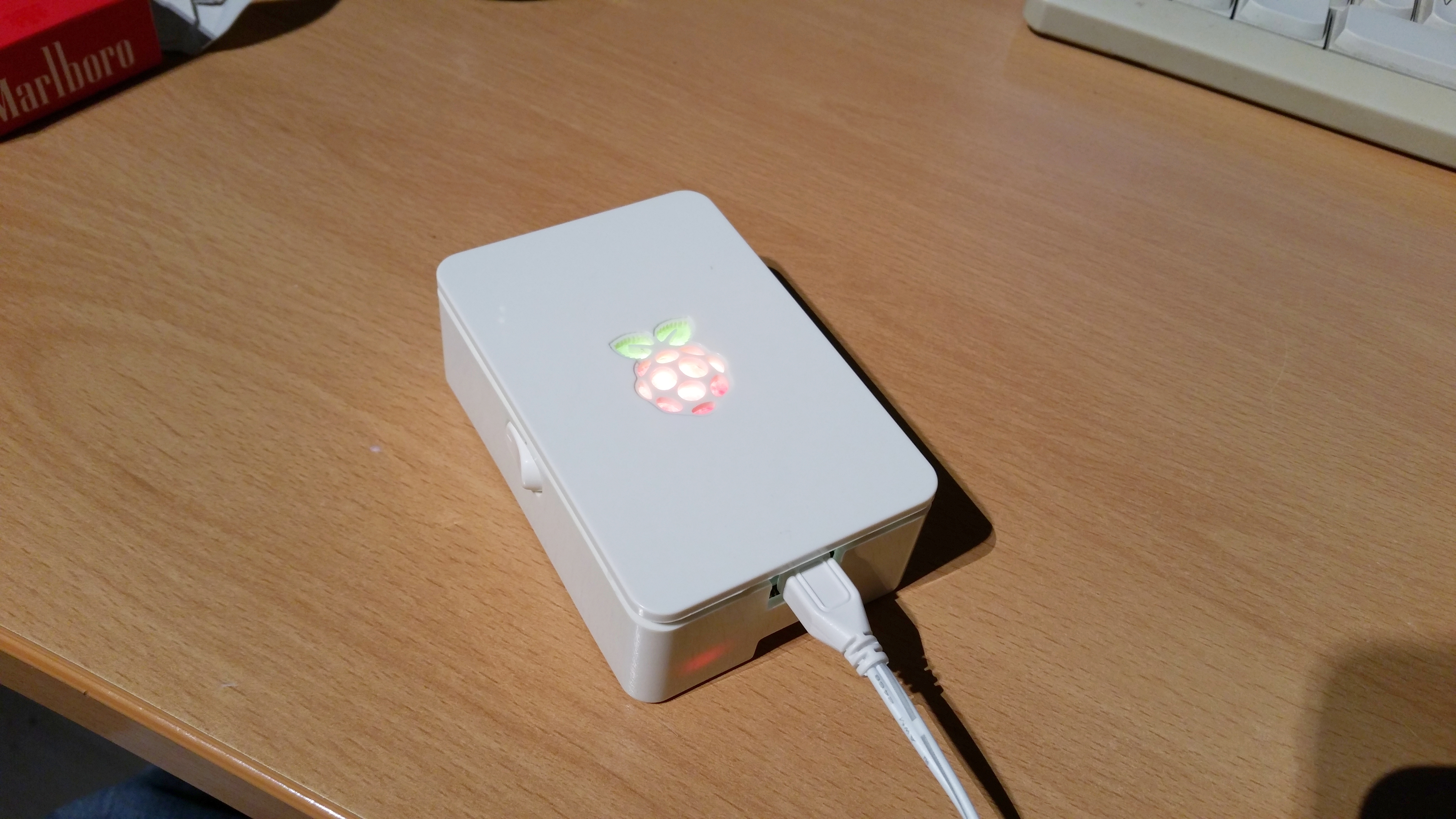
The case has a cut-out RPi-logo on top, the PowerBlock can run a LED with status information. Simple equation... I took some paper left from my kid's lantern crafting stuff and glued it under the logo.
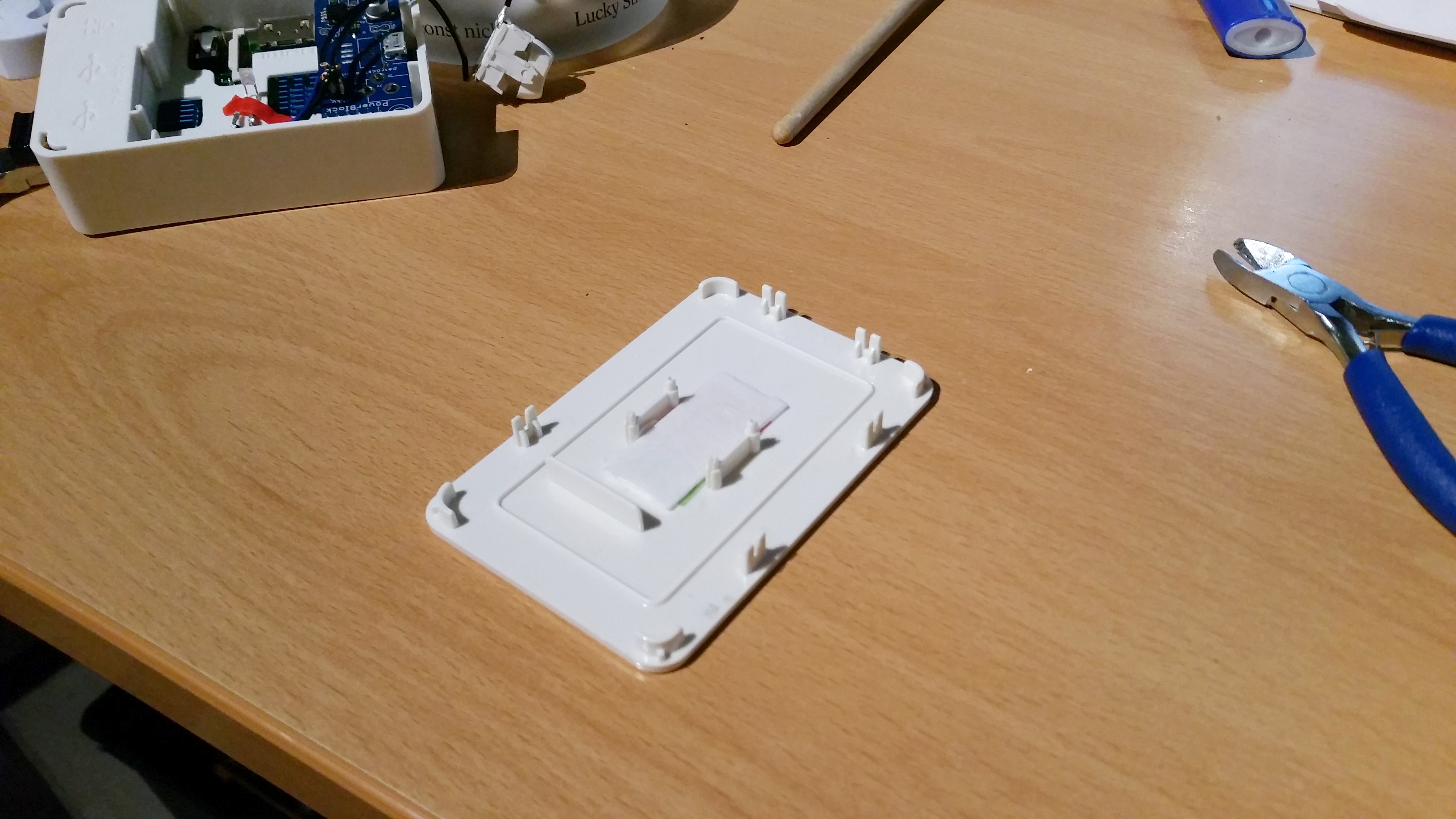
After a first check I had to admit, that a white 12,000mcd LED without any dimming is damn bright. So I glued some additional layers of 120g paper onto it, until the brightness stopped to hurt my eyes ;)
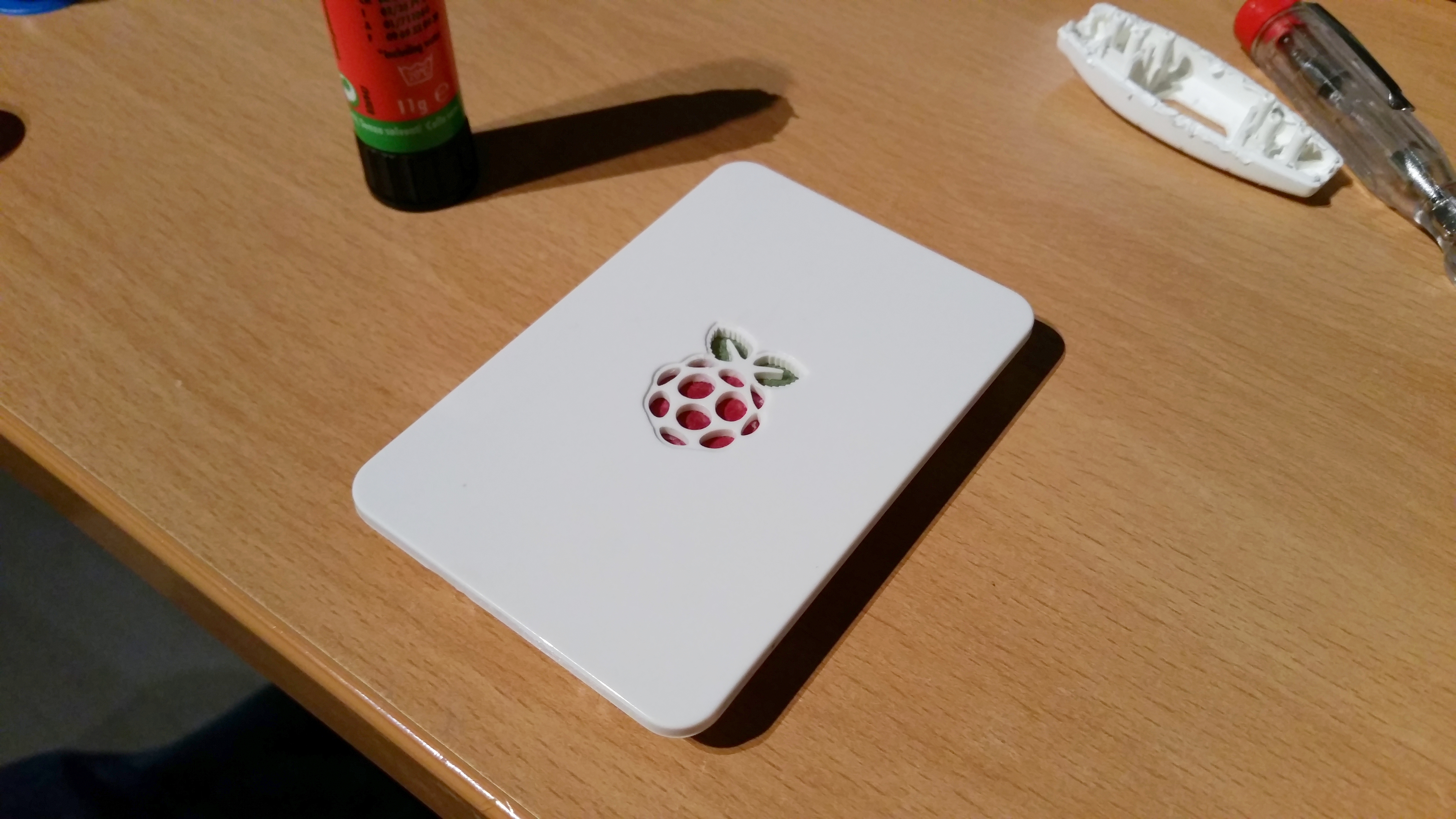
Pretty nifty, eh?
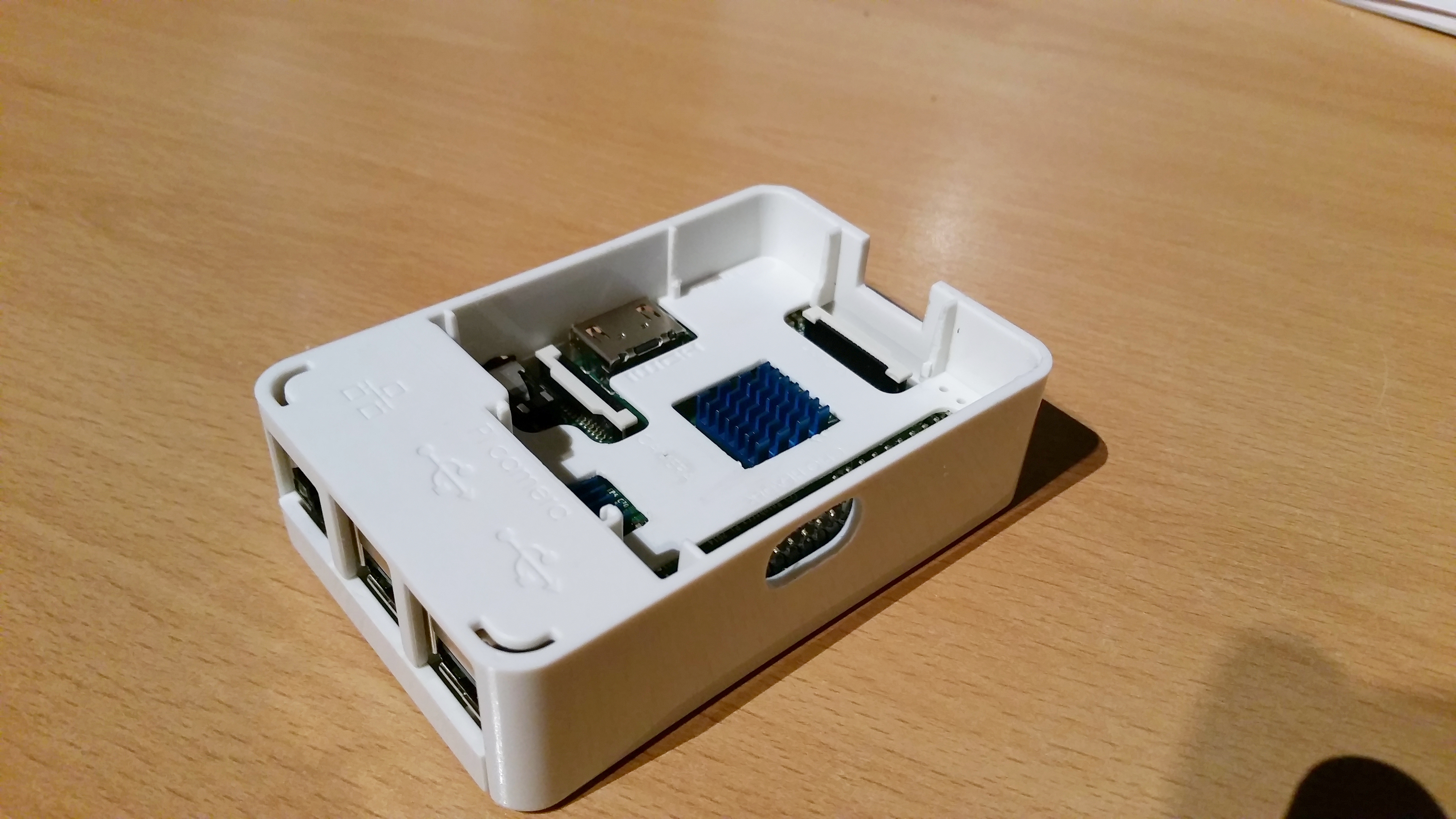
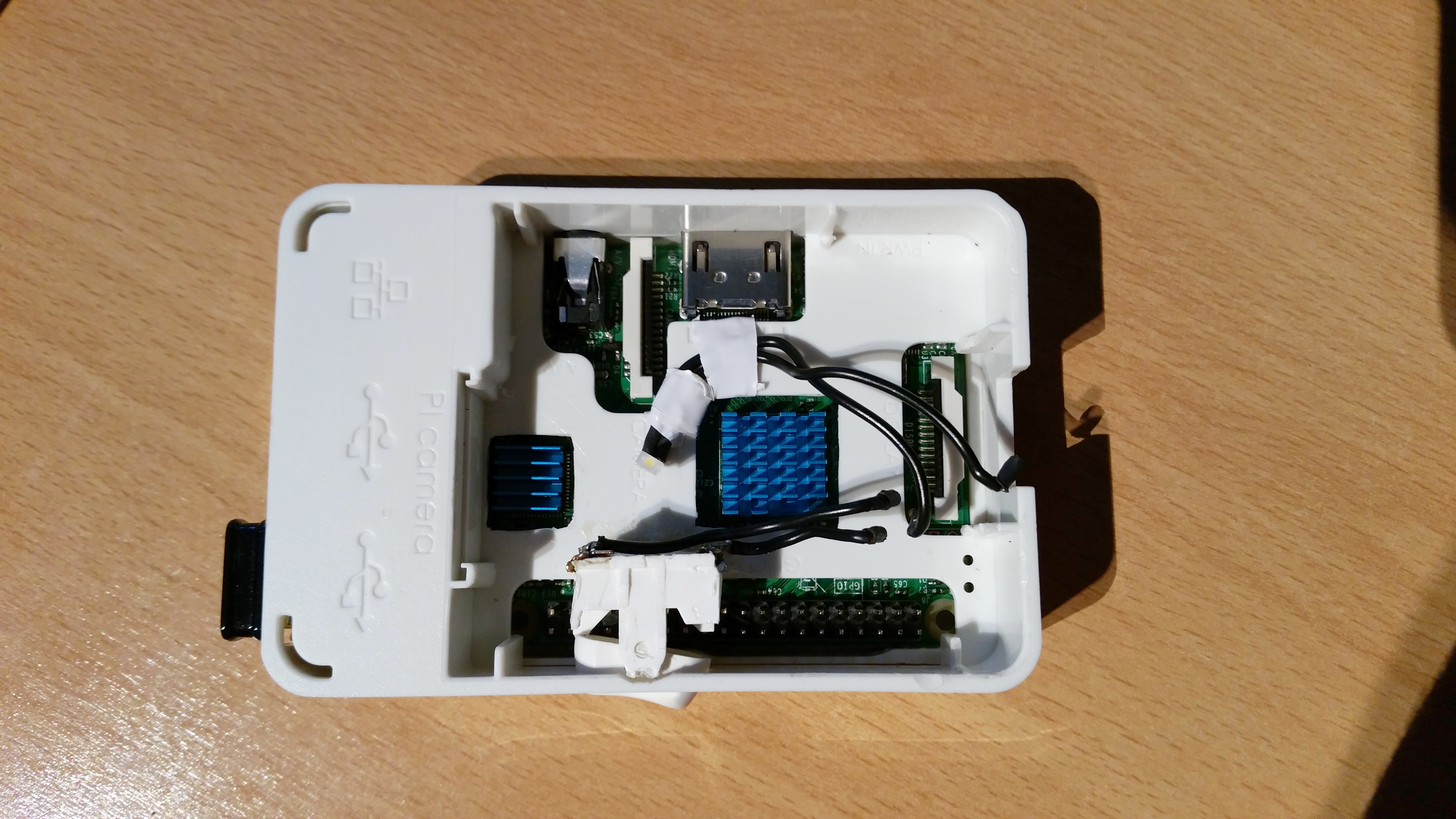
For all my stuff to fit in, I had to reshape the case a little. First, my version of the OneNineDesign case did not come with a cut-out for a memory-heatsink. I wanted to be better safe than sorry, so I cut a fitting hole in. The case was also designed for the first-gen Pi. They moved the SoC a little on the new board, so I had to widen that, too. The toggle switch was a little harder to realize. Above the HDMI-Slot and Audiojack, there was too little space to fit in. I also feared, that the cable wouldn't fit in with the switch directly above the slot. On the front I needed all the space for the PowerBlock and its micro-USB port. The back is full of ports, so d'uh. On the other side of the case, the GPIO pins of the Pi were in the way. But as this was the only realistic place to put the switch, I decided to cut the pins off (at least as much that I could fit the switch above it). One shall forgive me for that ;) The hole was cut with a die grinder.
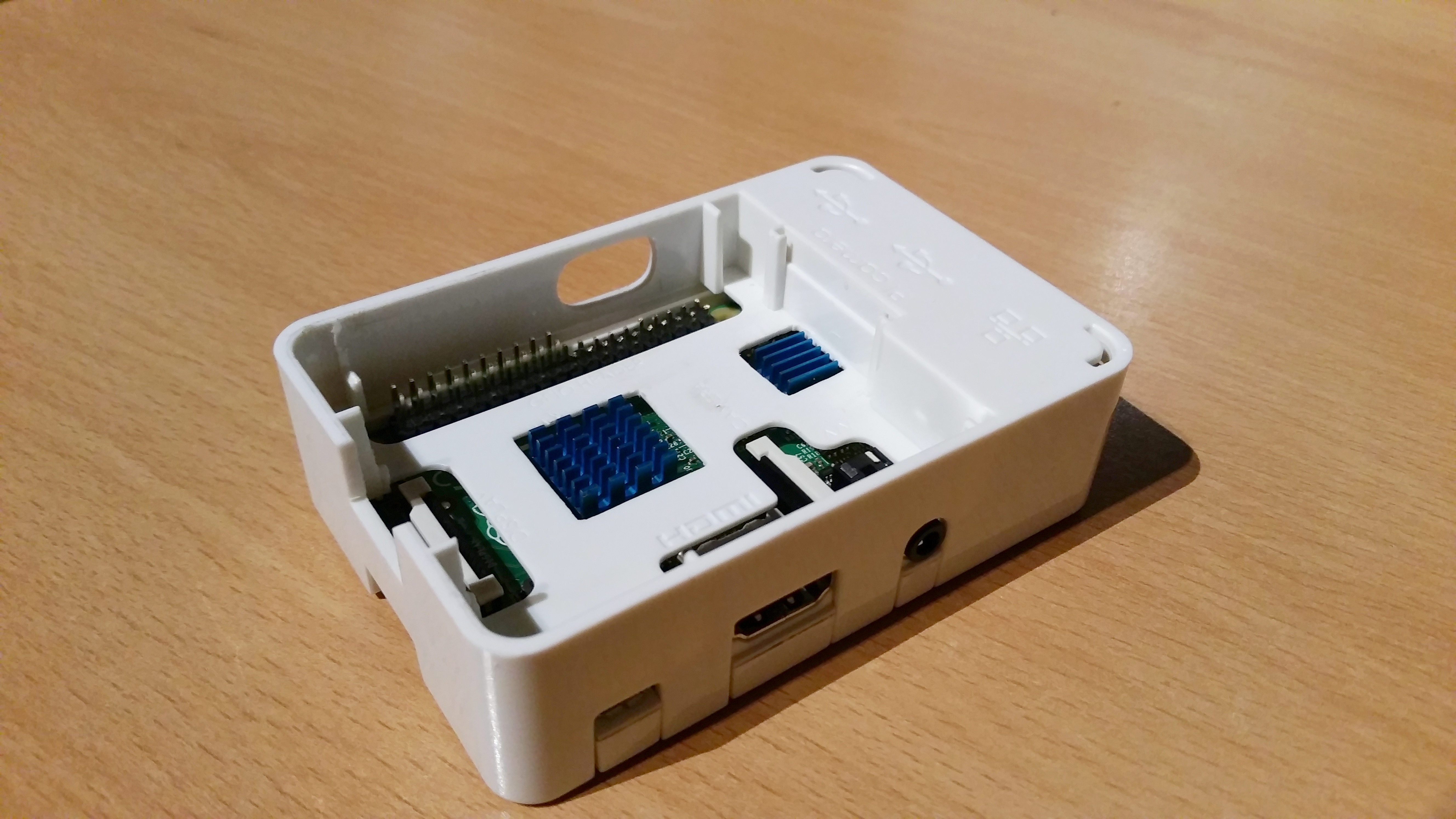
For the extension board I had to cut the little plastic poles on the inner sides of the case until the board sat down all the way on the pins. It also needed a hole for the micro-USB plug, which has to be connected to the extension board, rather than the Pi.
Time to wire the components. Nothing special here, except that I decided to not solder the LED and the switch onto the pins of the PowerBlock. Instead, I made myself some "plugs" or "connectors" or whatever you want to call it out of shrink hoses and cable end sleeves. Don't ask how many tries I needed to get this right. But at the end, this solution works pretty good. And yes, the switch looks kind of messed up. I don't have a picture of the original casing of the switch, but believe me: A high security prison is less secured than this little bastard was in it's original case.
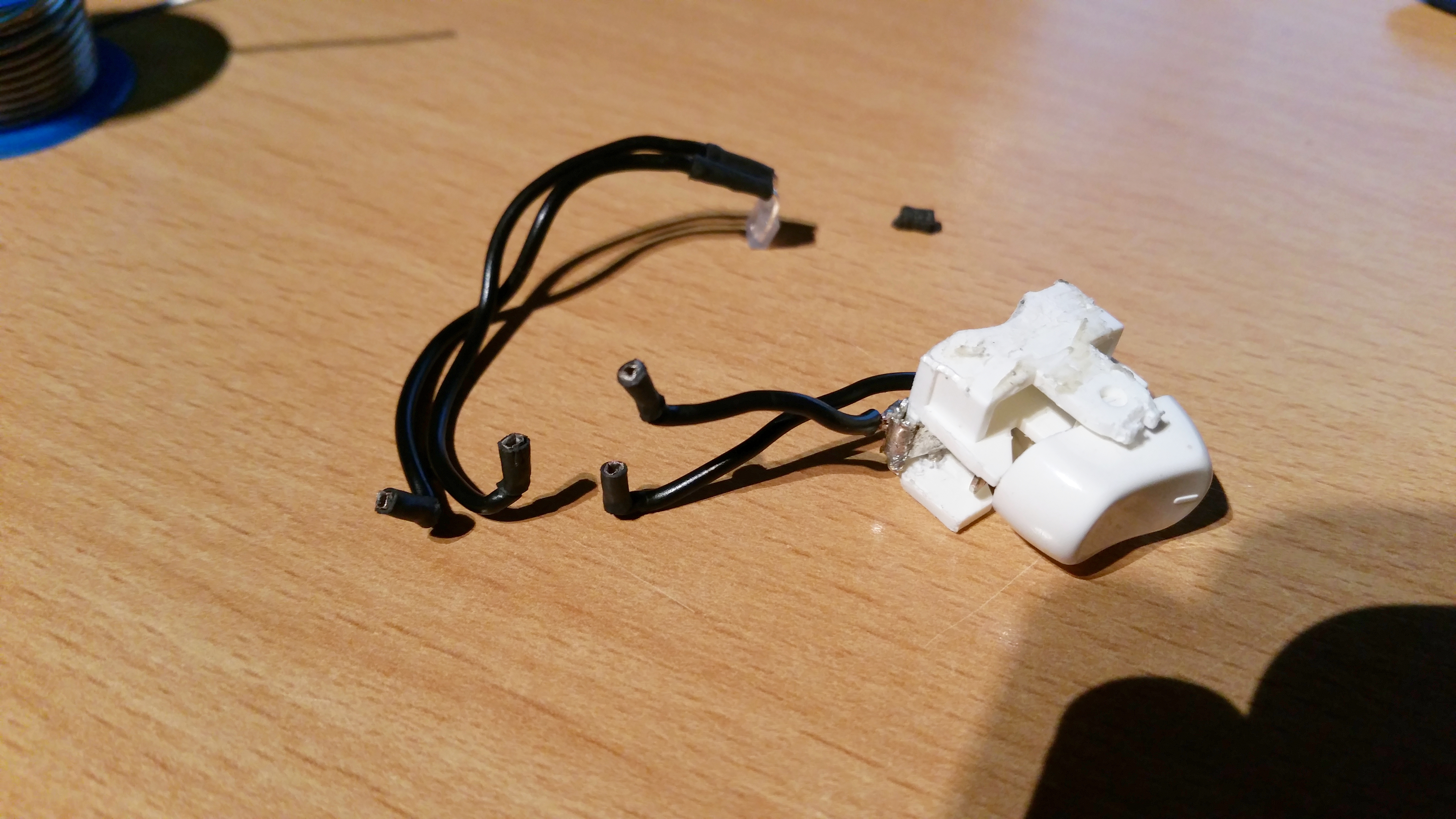
Ah, working with professionals. I glued the switch and I taped the LED. Fair enough.
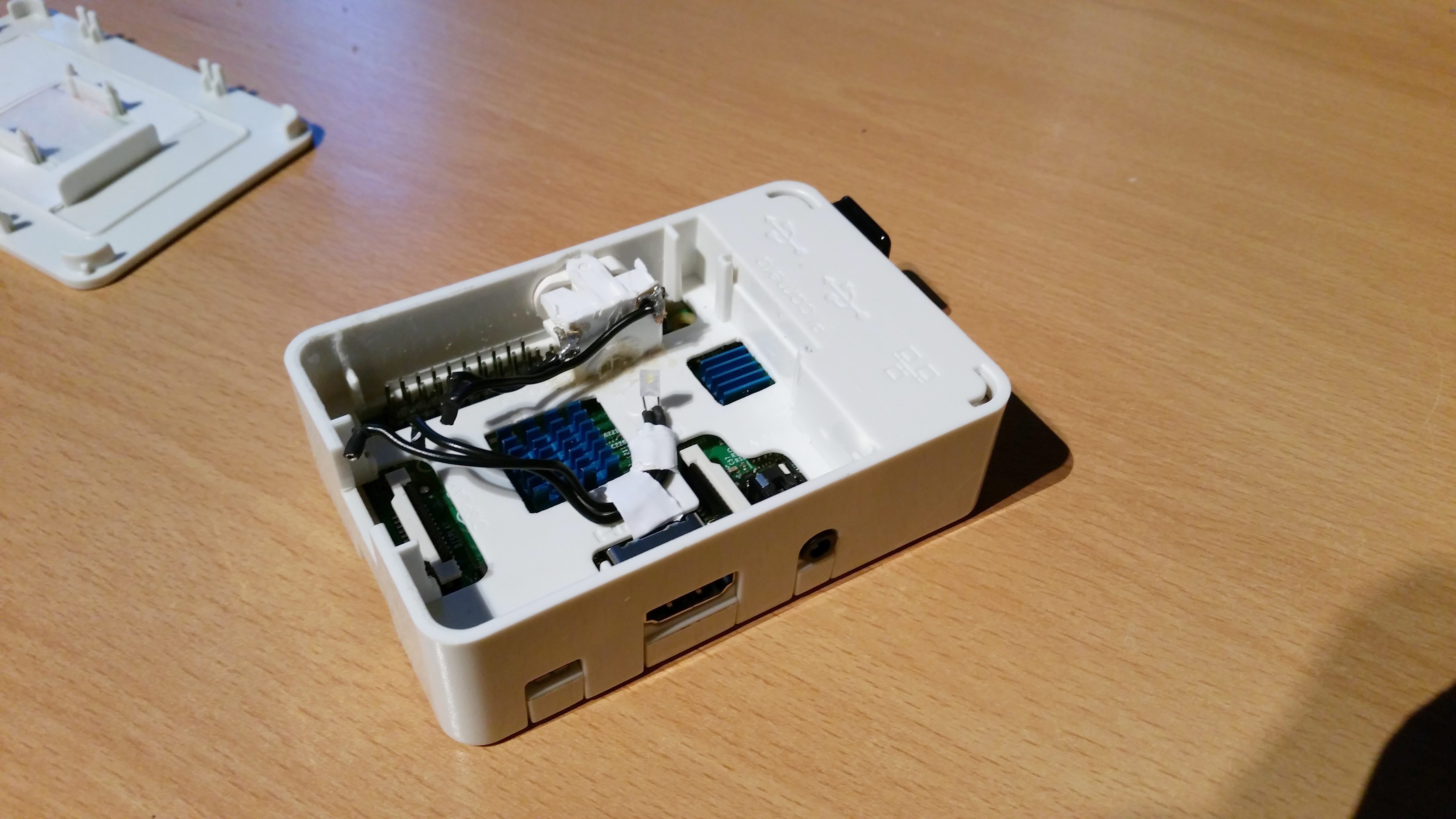
The last step: I racked the PowerBlock on the Pi and connected everything. Time for a test...
Turned off
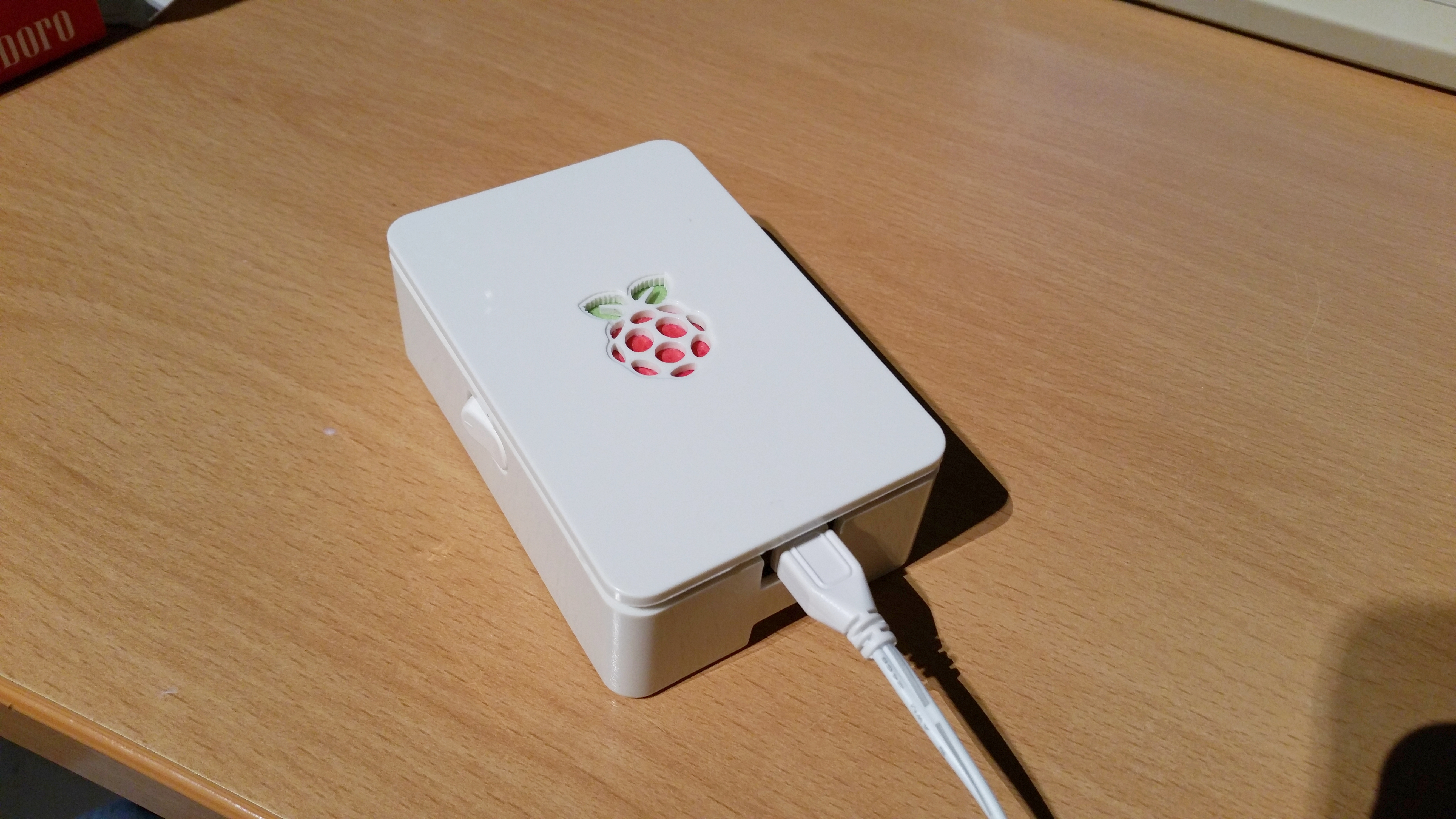
Turned on
For the switch to properly function, one has to compile the driver software into whatever OS one is running. I won't explain this here in detail, but for the reference: You have been warned ;)